
Construction & Building Material Blog

0%

Choosing the right Structural Construction Connectors can decide whether a frame remains stable, aligned, and serviceable for decades. On a busy jobsite, the details are practical: a beam seat must carry load, a splice plate must fit tightly, and an anchor bolt must resist movement. Small errors can create visible cracks, uneven joints, or costly delays. This guide examines China’s top 10 types of structural construction connectors used in steel, concrete, timber, and mixed-material projects.

The selection process should consider load direction, material strength, corrosion exposure, installation access, and inspection requirements. Common options include bolts, welded connectors, angle brackets, base plates, anchor systems, shear connectors, and specialized seismic components. Their performance depends on more than product appearance. Grade markings, coating thickness, hole tolerance, weld quality, and torque control all require careful verification. Manufacturer test reports and project drawings provide useful evidence, but they should not replace engineering judgment. No single ranking fits every building.

Experienced contractors often discover that the cheapest connector is not the lowest-cost choice. Installation time matters. Replacement access matters more than expected. A connector hidden behind concrete deserves extra attention. This guide therefore compares practical advantages, limitations, typical applications, and quality-control points for each type. Some classifications may overlap, and regional practices can differ. That uncertainty is worth acknowledging. Engineers should confirm final selections against structural calculations, approved specifications, and applicable building standards before construction begins.
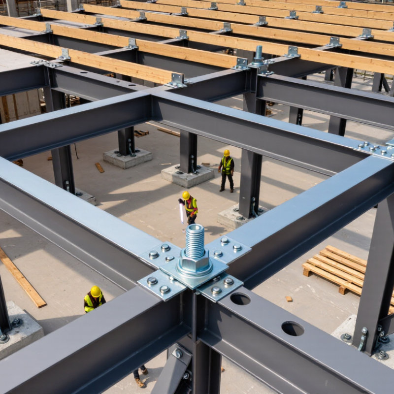
China Top 10 Types of Structural Construction Connectors

China’s Top 10 Structural Connectors: Functions, Materials, and Load Paths

China Top 10 Types of Structural Construction Connectors

China’s Top 10 Structural Connectors: Functions, Materials, and Load Paths

Structural connectors transfer forces between steel, concrete, timber, and masonry. Their shape matters, but the load path matters more. Anchor bolts carry tension and shear from columns into concrete foundations. Base plates spread compression and reduce local concrete stress. Gusset plates connect bracing members and redirect wind or seismic forces. Angle brackets provide compact support at beam and wall junctions. Beam clamps attach secondary steel without drilling the main member.

Column splice plates join stacked sections and pass axial forces through bolts or welds. Shear tabs transfer beam reactions into columns, usually through bolted connections. Moment connections resist bending and rotation, requiring careful weld and bolt detailing. Hold-down anchors secure timber walls against uplift during strong winds. Rebar couplers join reinforcing bars where lap lengths are limited, transferring tension through mechanical threads.

Common materials include carbon steel, galvanized steel, stainless steel, ductile iron, and engineered alloys. Galvanizing helps protect exposed connectors from moisture, but damaged coatings need attention. Stainless steel suits aggressive environments, although its higher cost can change the design decision.

Load capacity depends on bolt grade, weld quality, edge distance, embedment, and installation accuracy. A small misalignment can create unexpected prying forces. Real projects are rarely perfect.

Field verification remains essential, especially when concrete strength or reinforcement placement differs from drawings. A connector may look oversized, yet still perform poorly if the surrounding material fails first.

Bolted Connectors: Grades 8.8–12.9, Pretension, and Shear Capacity

China Top 10 Types of Structural Construction Connectors

Bolted connectors are judged by more than nominal strength. ISO 898-1:2013 lists minimum tensile strengths of 800, 1,000, and 1,200 MPa for grades 8.8, 10.9, and 12.9. Their yield strengths are approximately 640, 900, and 1,080 MPa. Higher grade does not automatically mean better performance. Connection geometry, hole clearance, bearing, and installation quality still control the result.

Pretension creates clamping force across the joint. EN 1993-1-8 defines the initial preload as 0.7 fub As for preloaded assemblies. The 2020 RCSC Specification also requires calibrated installation procedures and verification. A torque value alone is weak evidence because friction can vary widely between threads, washers, and coatings. On site, a calibrated tensioning method matters more than a clean calculation sheet.

Shear capacity depends on the bolt area and the governing design code. Eurocode calculations use a resistance factor linked to ultimate strength and bolt diameter. For example, an 8.8 bolt provides about 480 MPa of nominal shear stress before code reductions, while a 12.9 bolt can approach 600 MPa under simplified assumptions. These figures are not final design capacities. Slip, prying, thread location, and joint eccentricity may reduce them sharply. I have seen designs overvalue grade 12.9 and undervalue installation control. That assumption is often too tidy.

Welded Connectors: GB 50017 Design Classes, Heat Input, and Failure Modes

Welded connectors remain central to structural steelwork, especially where compact joints transfer high tension, shear, or moment. Under GB 50017-2017, weld quality grades should match structural importance, stress conditions, inspection requirements, and failure consequences. Higher-grade welds demand stricter workmanship and non-destructive testing. That choice affects cost, schedule, and reliability.

Heat input deserves closer control. The practical calculation uses Q = ηVI/v, where voltage, current, travel speed, and process efficiency govern energy entering the joint. Excessive heat can enlarge the heat-affected zone, reduce toughness, and increase distortion. Insufficient heat may leave incomplete fusion or penetration. ISO 5817 provides quality levels for weld imperfections, while ISO 17635 guides suitable non-destructive testing methods. These references support consistent inspection, but field conditions still complicate execution.

Failure rarely begins with one dramatic event. Common modes include throat shear, weld-metal cracking, HAZ cracking, lamellar tearing, fatigue cracking, and brittle fracture at low temperatures. The World Steel Association reported approximately 1.89 billion tonnes of crude steel production in 2023, showing the scale of steel construction and its quality-control challenge. Site records should capture consumables, preheat temperature, interpass temperature, welder qualification, and repair locations. Small details matter. A design may satisfy GB 50017 calculations, yet poor fit-up or delayed inspection can weaken the real connector. More conservative assumptions are sometimes necessary.

China Top 10 Types of Structural Construction Connectors - Welded Connectors: GB 50017 Design Classes, Heat Input, and Failure Modes

No. Welded Connector Type Typical Structural Use Typical GB 50017 Design Class* Common Weld Form Indicative Heat Input
(kJ/mm)
Main Design Action Primary Failure Modes Key Control Measures
1 Complete-Joint-Penetration Butt Connector Spliced flange plates, web plates, box columns, and heavily loaded members Primary load-bearing CJP groove weld 0.8–2.5 Axial force, bending, shear Lack of fusion, incomplete penetration, weld-metal cracking, lamellar tearing, fatigue cracking Qualified WPS, controlled joint preparation, preheat where required, volumetric NDT, low-hydrogen consumables
2 Partial-Joint-Penetration Groove Connector Secondary beam splices, stiffener attachments, and members with limited force demand Primary or secondary, subject to force demand PJP groove weld 0.6–1.8 Axial force and bending Insufficient effective throat, incomplete fusion, local cracking, brittle fracture under cyclic loading Use the specified effective throat, verify access and root geometry, inspect critical zones, avoid unqualified size reduction
3 Fillet-Welded T-Connector Beam-to-column plates, brackets, transverse stiffeners, and angle connections Primary or secondary Double fillet weld 0.4–1.2 Shear and eccentric tension Throat fracture, weld-end cracking, plate tear-out, local buckling, distortion Check effective weld length and throat, provide end returns where appropriate, control weld sequence and distortion
4 End-Plate Beam-to-Column Connector Rigid or semi-rigid moment-resisting beam-column joints Primary seismic or gravity frame CJP and fillet weld combination 0.7–2.0 Moment, shear, axial force Panel-zone yielding, weld fracture, bolt-hole bearing, end-plate yielding, cyclic fatigue Design the complete load path, reinforce panel zones where necessary, sequence welds symmetrically, inspect CJP welds
5 Column-Base Plate Connector Steel column-to-foundation assemblies and transfer structures Primary gravity or seismic CJP or fillet weld 0.6–1.8 Compression, uplift, shear, moment Weld fracture, base-plate bending, anchor-rod failure, concrete bearing or breakout Coordinate welds with anchor rods, verify load transfer and stiffeners, control heat near thick plates, inspect concealed welds before grouting
6 Web-Stiffener Connector Plate girders, crane girders, box sections, and concentrated-load regions Primary or fatigue-sensitive Fillet or PJP groove weld 0.4–1.4 Web shear, patch loading, compression Weld toe fatigue, web crippling, local buckling, restraint cracking Smooth weld terminations, adequate stiffener fit-up, balanced welding, fatigue-detail review
7 Cover-Plate Flange Connector Built-up beams, plate girders, and strengthened flange regions Primary flexural member Continuous fillet or groove weld 0.5–1.6 Flange tension or compression Weld interface fracture, lamellar tearing, flange distortion, fatigue at weld ends Detail weld ends carefully, assess through-thickness properties for thick plates, limit restraint, use staged welding
8 Hollow-Section Branch Connector Trusses, space frames, tubular roofs, and pipe-column assemblies Primary truss or space-frame Perimeter fillet or groove weld 0.3–1.0 Axial force and chord bending Chord plastification, punching shear, local wall buckling, weld toe fatigue Maintain correct branch angle and fit-up, provide complete perimeter welding where designed, inspect inaccessible profiles
9 Shear Tab and Seat Connector Simple beam-to-column or beam-to-girder shear connections Secondary or nominally pinned Fillet weld 0.3–0.9 Vertical shear and accidental tension Weld shear failure, plate yielding, bolt bearing, block shear, seat bending Check required rotation, provide adequate weld length, verify bolt and plate limit states, protect against erection damage
10 Embedded-Plate Steel-to-Concrete Connector Steel stairs, façade supports, equipment frames, and transfer brackets Primary or secondary, depending on load path Fillet or CJP weld to embedded plate 0.4–1.3 Shear, tension, moment Weld fracture, anchor failure, concrete breakout, plate bending, corrosion at interfaces Coordinate reinforcement and embedded items, verify edge distances and anchorage, seal exposed interfaces, inspect before concealment
Notes: The design classes shown are practical engineering categories rather than a replacement for the project classification required by the applicable Chinese standards. GB 50017 primarily governs the structural design and detailing of steel members and connections; weld quality, inspection, material, and fabrication requirements should also be checked against the applicable welding and inspection standards. Heat-input values are indicative fabrication ranges, not code limits. Actual heat input depends on welding current, voltage, travel speed, process, plate thickness, joint restraint, and the qualified welding procedure.

Anchors, Plates, and Dowels: Embedment Depth, Edge Distance, and Pullout

China Top 10 Types of Structural Construction Connectors

Anchors, plates, and dowels perform differently under structural loads. Anchors resist tension and shear through steel strength, bond, or mechanical interlock. Embedment depth matters greatly. Too little depth can cause concrete cone failure or pullout. Extra depth does not always solve the problem. Rebar clashes, weak concrete, and poor cleaning can reduce capacity.

Edge distance is equally important. An anchor placed too close to an edge may split the concrete before reaching its rated load. Nearby anchors can also interact, especially when spacing is tight. Base plates spread compression across the concrete, but they do not automatically increase anchor pullout resistance. Dowels transfer shear between connected elements. Their performance depends on development length, grout quality, hole alignment, and surrounding reinforcement.

Tips: Check drawings against the real site before drilling. Measure concrete thickness and edge distances. Confirm the specified embedment with a depth gauge. Remove dust from drilled holes. Record torque, temperature, concrete condition, and visible cracks. A clean installation still needs inspection.

In practical work, assumptions often fail. A thick-looking slab may contain hidden voids or congested reinforcement. Pullout testing can reveal problems that visual checks miss. Design values should follow the applicable structural standard and verified project data. When loads are uncertain, a qualified structural engineer should review the connection. Conservative detailing is useful, but careless overdesign can create new installation risks.

Selection and Compliance: GB/T 3098.1, GB 50011, Testing, and Corrosion Data

Choosing among the ten common types of structural construction connectors requires more than checking diameter and strength. GB/T 3098.1 defines mechanical property requirements for many carbon and alloy steel fasteners, including tensile strength, proof load, hardness, and thread performance. In practice, engineers should match these values with the connector’s load path and installation method. A certificate alone is not enough.

GB 50011 makes seismic behavior central to structural selection in relevant Chinese projects. Connection details must support ductility, anchorage, and reliable force transfer during repeated loading. Testing should include dimensional inspection, material verification, torque or tension checks, and, where required, cyclic or pull-out testing. GB/T 10125 can support laboratory evaluation of atmospheric corrosion resistance. Still, salt-spray results do not perfectly reproduce every construction site.

Corrosion data deserves closer attention. The NACE IMPACT study estimated annual global corrosion costs at about US$2.5 trillion, equal to roughly 3.4% of global GDP. It also reported that 15–35% of this cost could be reduced through better corrosion management. For connectors near moisture, chlorides, or dissimilar metals, coating thickness, cut edges, drainage, and inspection records matter. I have seen sound calculations weakened by poor washers and trapped water. That detail is easy to miss. Field exposure, maintenance access, and incomplete test records should remain visible in the final selection.

FAQS

What is the main purpose of structural connectors?

They transfer forces between steel, concrete, timber, and masonry. A connector’s shape matters. The complete load path matters more.

How do anchor bolts and base plates work together?

Anchor bolts transfer tension and shear from columns into concrete foundations. Base plates spread compression across the concrete. Poor embedment can still cause failure.

Which materials are commonly used for structural connectors?

Common choices include carbon steel, galvanized steel, stainless steel, ductile iron, and engineered alloys. Galvanizing protects exposed steel from moisture. Scratched coatings need attention.

Does a higher bolt grade always provide better performance?

No. Higher strength does not guarantee a stronger connection. Hole clearance, bearing, edge distance, and installation quality remain important. A stronger bolt may expose a weaker plate.

Why is bolt pretension important?

Pretension creates clamping force across the joint. It can reduce slip and improve contact between connected parts. Torque alone is imperfect evidence. Friction changes.

What controls the real shear capacity of a bolted connection?

Capacity depends on bolt area, strength, joint geometry, and the governing design rules. Thread location, prying, slip, and eccentricity can reduce resistance. A neat calculation may still miss site conditions.

Why must welding heat input be controlled?

Excessive heat can enlarge the affected zone and increase distortion. Insufficient heat may cause incomplete fusion or penetration. Record voltage, current, travel speed, and temperatures. Small records matter.

What common problems affect welded connectors?

Typical problems include throat shear, cracking, lamellar tearing, fatigue, and brittle fracture. Poor fit-up can weaken an otherwise acceptable joint. Inspection timing matters. Repairs should be documented.

Why is field verification necessary for structural connectors?

Drawings may not match actual concrete strength or reinforcement placement. Small misalignment can create unexpected prying forces. Check bolt installation, weld quality, embedment, and surrounding materials. Real projects are rarely perfect.

Conclusion

Structural Construction Connectors are essential for transferring forces safely between steel, concrete, and other structural components. China’s top connector types can be evaluated by their function, material, connection method, and intended load path. Bolted connectors commonly use grades 8.8 to 12.9, with performance depending on pretension, friction, bolt arrangement, and shear capacity. Welded connectors require attention to the design classes of GB 50017, heat input, weld quality, residual stress, and possible failure modes such as fracture, buckling, or fatigue.

Anchors, connection plates, and dowels must be selected according to embedment depth, edge distance, concrete strength, and resistance to pullout or shear failure. A reliable selection process should also consider GB/T 3098.1, GB 50011, project-specific loading, installation conditions, inspection, and corrosion exposure. Testing and documented corrosion data help verify long-term performance, while proper detailing and quality control ensure that each connector functions as part of a safe and continuous structural system.

Oliver

Oliver

Oliver is a dedicated marketing professional with an exceptional depth of knowledge about our company's innovative products. With a keen eye for detail and a passion for staying ahead of industry trends, he consistently offers valuable insights through our company's professional blog articles.......